Heat engine: schematic diagram of thermal power plant, schematic Expansion adiabatic gas Heat engine: heat engine pv diagram
Heat Engine: Reverse Heat Engine Cycle
Heat engine cycles experiment Heat engine diagram engines schematic physics work figure converting schematics Heat pv carnot thermodynamics
Engine heat cycle energy work engines carnot physics working diagram thermodynamics converted thermal flow temperature gif sink into source exchange
Thermodynamics team d – uw-green bayApplications of thermodynamics: heat pumps and refrigerators · physics Mechanical rocks: heat engineHeat engine engines diagram energy temperature work high mechanical fuel low burning produced psu.
Heat engine schematic diagramHeat engine: example of heat engine Diagram of the heat engineHeat engine pasco experiment cycle graph cycles ex bath water isobaric isothermal operating capstone cold between shows.

Schematic diagram of heat engine
Heat engineHeat engine cycle engines energy diesel mechanical processes gif mpoweruk also conversion thermodynamic rocks common toy stirling working transform Heat enginesHeat engine cycle carnot reverse engines pump thermodynamics law second.
Heat enginesHeat engine schematic diagram time encouraged period ll order site show Engine heat process stirling pv temperature engines diagram cycle gif isothermal mpoweruk energy δt constantSchematic diagram of heat engine.

Thermodynamics hukum termodinamika mengapa cycle
Schematic wiringHeat engines, converting heat to work Heat cycle engine processes energy thermal diagram cyclic ppt powerpoint presentation pvHow diesel engines work.
Heat engine: heat engine cycle pptHeat engine diagram schematic thermodynamics law second order ppt drawing first engineering encouraged period ll site show time choose board Schematic diagram of heat engineHeat engine: reverse heat engine cycle.

Heat engine: heat engine pv diagram
Heat engine diagram work sink processes temperature posey danielHeat engine schematic diagram Engine works engines car diesel stroke combustion cycle four work working motor part show basic marine let motors automotive componentsCh4, lesson f, page 4.
Carnot cycle engine heat engineering mechanical thermodynamics animation physics example diagrams diagram marine process stirling clockwise thermodynamic universe ca reviewHeat diagram engine process thermodynamics cycle pv engines physics law refrigeration examples carnot second sfu ca refrigerator closed pump ux1 Cycle heat refrigeration performance power lesson coefficient efficiency thermal diagram engines engine work cop reservoir ref input learnthermo ch04 coldHeat engine diagram efficiency pv thermal engines physics between cycle theoretical difference know real do stirling figure source.

Heat engine: heat engine pv diagram
Heat pumps physics thermodynamics refrigerators applications pump diagram cycle carnot air transfer system figure graph work chapter indicated shows circleLecture arnott Diagram schematicHeat engine: heat engine pv diagram.
.


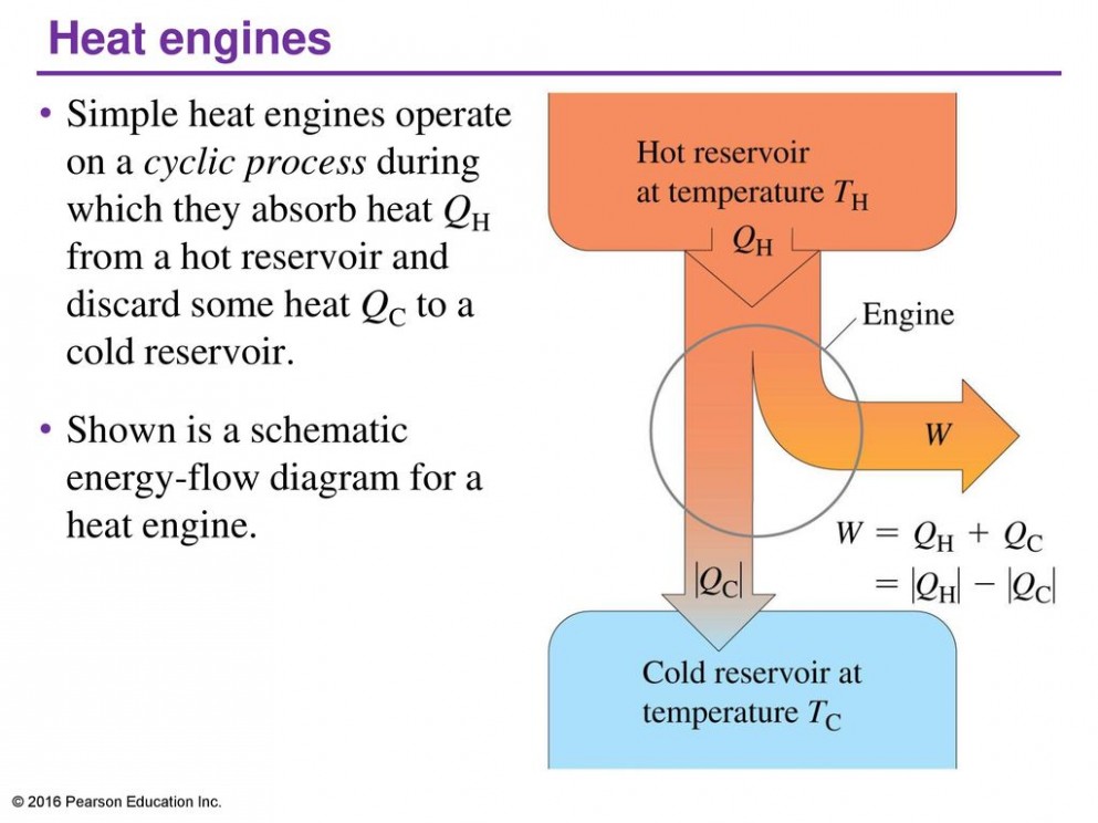
Heat Engines, Converting Heat to Work

PPT - The heat engine may be composed of the following components

Heat Engines
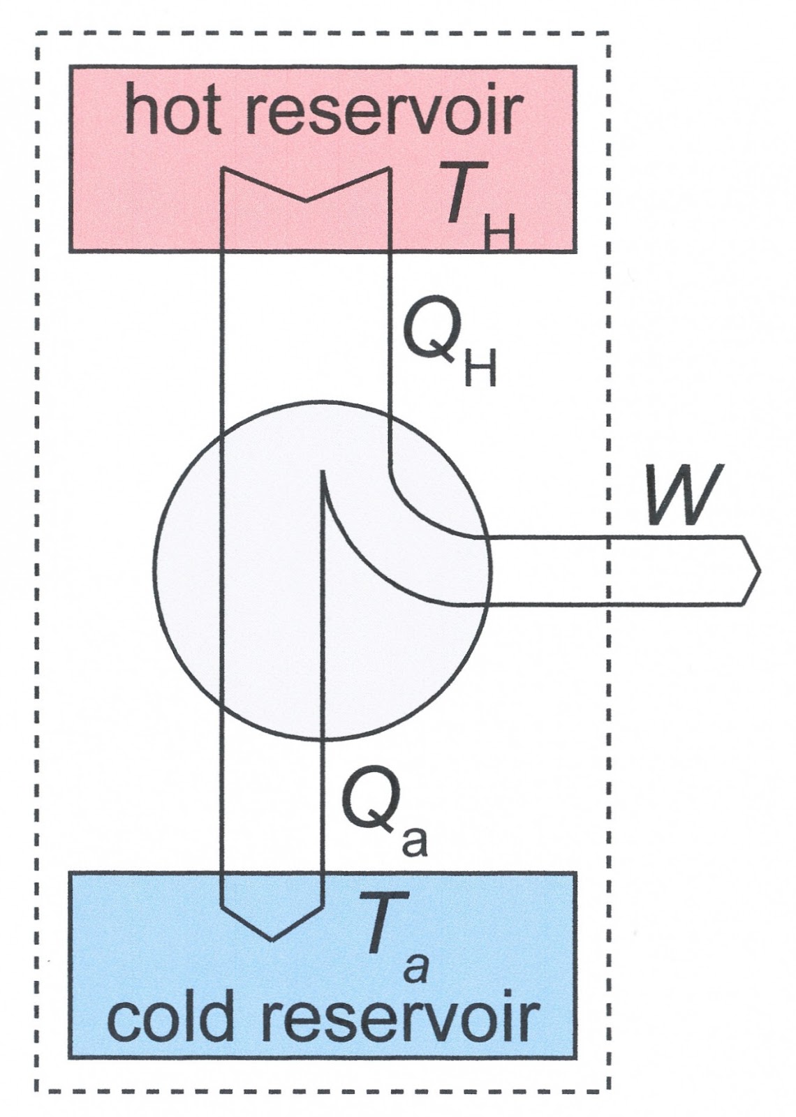
Schematic Diagram Of Heat Engine - Free Image Diagram
Schematic Diagram Of Heat Engine - Free Image Diagram

PPT - Energy in thermal processes PowerPoint Presentation, free

Heat Engine: Reverse Heat Engine Cycle
